Using Snap & Grid In Isometric Sketches
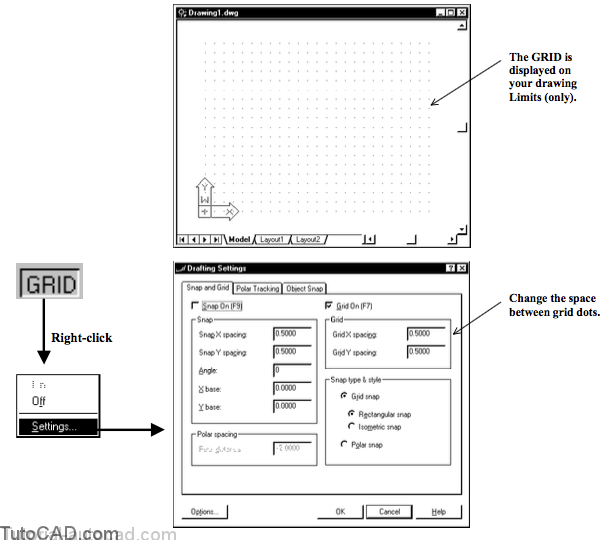
You can turn On the GRID in the status bar to see an array of dots on your screen at a fixed spacing in the X and Y directions.
- use the GRID as a visual frame of reference (these dots in your GRID will not appear when you Plot).
- the GRID is displayed ONLY in the drawing Limits area.
- you may not see the GRID when you are zoomed out if the space between each dot is too small (too dense) to display.
- the GRID setting does NOT constrain your crosshair movement.
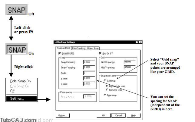
Turn On the SNAP tool in the status bar to constrain your crosshairs so they move only in specified steps.
When you select Grid snap for the Snap type & style your SNAP points are arranged like your GRID points
- but X & Y spacing for SNAP is independent of GRID spacing.
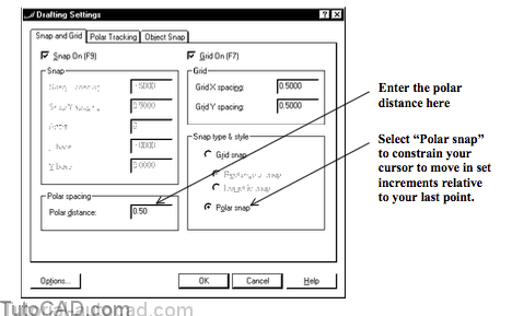
Selecting Polar snap as the Snap type & style constrains crosshairs relative to your last point (instead of using a fixed array of points).
- you can specify a Polar distance instead of X & Y spacing and you can specify Polar Angles on the Polar Tracking tab.
- you will be learning more about how to use the POLAR tool with the Polar snap setting later on in this document.
SNAP & GRID are practical tools for sketching 2D isometric representations of simple 3D objects (or schematic diagrams).
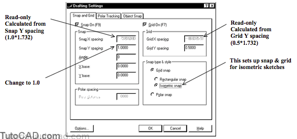
- select Grid snap as the Snap type & style and then select the Isometric snap radio button.
The X spacing (for both Snap & Grid) is calculated (read-only) using the value that you enter for Y spacing.
- X spacing = [Y spacing] ÷ tangent (30°) = 1.732 * [Y spacing] (for example, if Y spacing is 0.5 then X spacing would be 0.866).

PRACTICE USING SNAP & GRID IN ISOMETRIC SKETCHES
»1) Launch AutoCAD (if required). Close all other drawings (if other drawings are open).
»2) Pick File + New. Select Start from scratch and use nglish default settings. Pick OK to continue.
»3) Save the file as My sketch.dwg in your personal folder.
»4) Pick Tools + Run Script. Select the T204.scr script file in your personal folder and pick the Open button there to run this script. This sets several system variables to match the behavior illustrated in the exercises.
»5) Left-click on the SNAP & GRID status bar buttons to toggle these settings On.
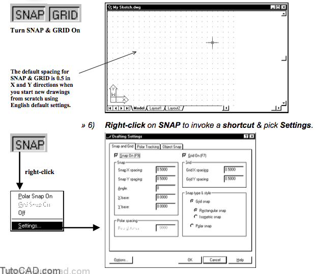
7) Select Isometric snap & then change the Snap Y spacing to 1.0 (from 0.5). Pick OK to put these changes into effect.
8) Pick Format + Drawing Limits. Press <enter> to use 0,0 (origin) as the lower left corner. Then enter 17,11 as the coordinates for the upper right corner.
9) Pick View + Zoom + All. Pick View + Zoom + Scale. Enter 0.8X to zoom out slightly.
10) Move you crosshairs about the screen and observe how your crosshairs hop between SNAP points.
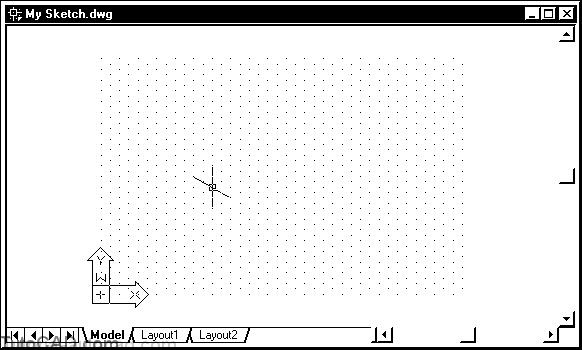
The GRID is displayed only over your current drawing limits which at this point is set up for a B size sheet (17×11 inches).
The SNAP points are only at every other GRID point because your SNAP spacing is twice that of GRID.
- SNAP & GRID spacing can be set independently.
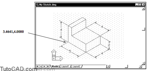
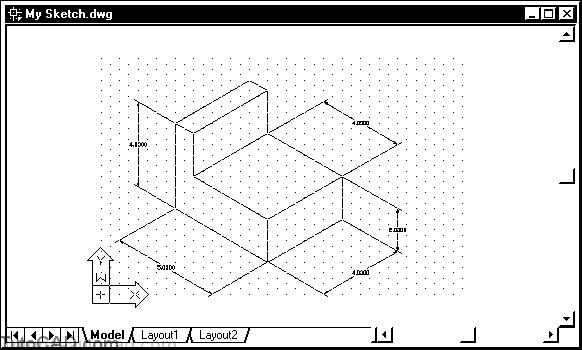
11) Use the Line command to sketch a simple isometric sketch to match the illustration below. Each LINE endpoint coincides with a SNAP point. Do not create the dimensions.
12) Pick Dimension + Aligned. Pick SNAP points at P1 then P2 then pick near P3 to place the dimension text.
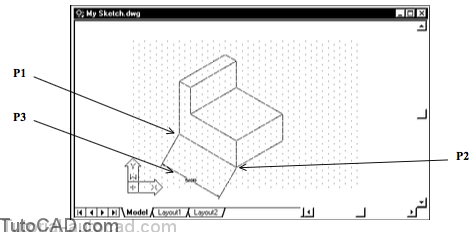
13) Pick Dimension + Oblique. Select the last dimension & press <enter>. Pick P4 & P5 for the oblique angle.
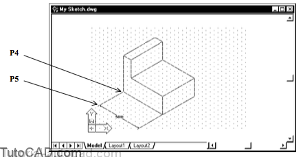
14) Use a similar technique to create the other dimensions.
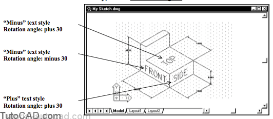
You can create special text styles for isometric sketches to make 2D TEXT appear as though it is actually in different 3D planes.
- define a text style with a positive 30° oblique angle and another style with a negative 30° oblique angle.
- a positive or negative 30° rotation angle for TEXT created using these two text styles make TEXT objects appear isometric.
Want to try it?
15) Use the Style command to define two new text styles called Plus (positive 30 oblique angle) and Minus (negative 30 oblique angle). Create the 0.75 high TEXT labels shown below using these styles & the rotation angles indicated. You can turn the SNAP setting Off to pick insertion points by eye and type the rotation angles shown.
16) Save the changes to your drawing then Close the file.