How to use Tracking With Parallel & Extension Osnaps
Free course how to use Tracking With Parallel & Extension Osnaps in AutoCAD
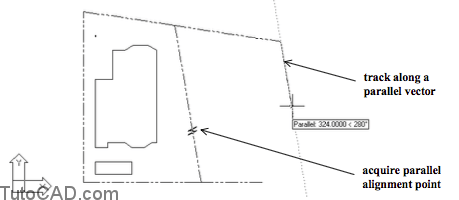
You can track using the Parallel osnap tool.
- acquire Alignment points using the Parallel osnap and you constrain the tracking vector parallel to the segment of interest.
- the Parallel osnap can avoid having to define a temporary UCS or create temporary construction objects (e.g. avoid Offset).
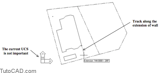
The Extension osnap lets you track along the extension of an existing object (even non-linear objects like ARCs).
- this can avoid having to create temporary construction objects (e.g. Lengthen existing LINEs) just to find the desired point.
- for example, you could track along the extension of a foundation wall LINE when the current UCS is not aligned with this wall.
Practice: tracking with Parallel & Extension osnaps tutorial in AutoCAD
- Close the drawing from the previous exercise if it is open.
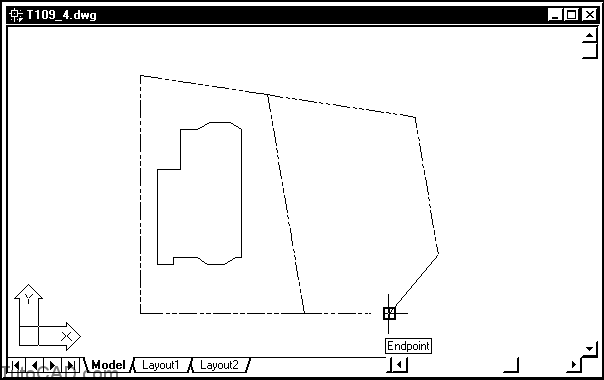
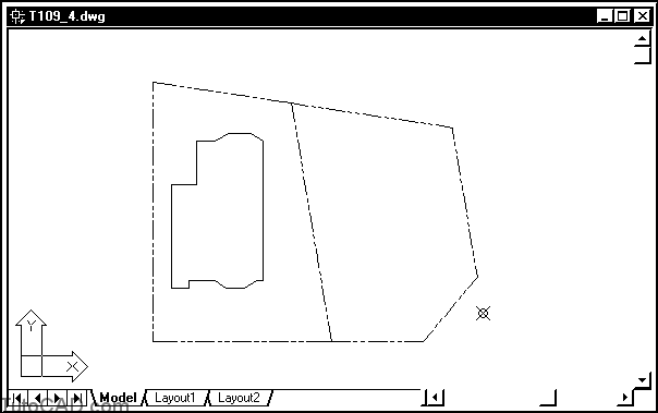
- Open the T109_4.dwg drawing in your personal folder.
You will use Parallel and Extension osnaps with tracking to complete the legal boundary for an adjacent site and add a survey marker POINT.

- Right-click on the OSNAP status bar button and select Settings in the shortcut. Check Extension and Parallel then uncheck Quadrant. Pick OK.
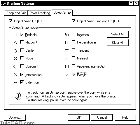
The Extension osnap is a practical running osnap to leave checked – the initial settings for running osnaps has Extension checked but the script you ran on page 6 (T109.scr) turned this osnap off.
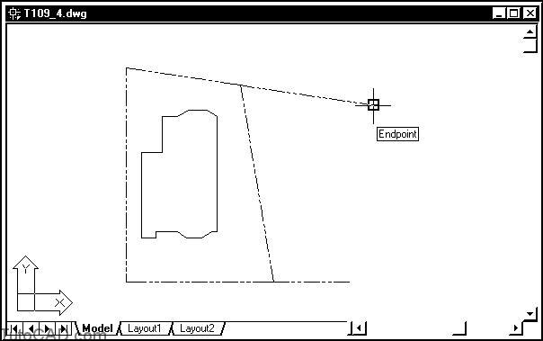
- Pick Draw + Line. Invoke the Endpoint osnap shown then left-click to use this as the start of the LINE.
- Invoke the Parallel osnap near P1 & hold your crosshairs over this marker to acquire it as an alignment point. Then move your crosshairs near P2.
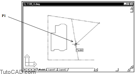
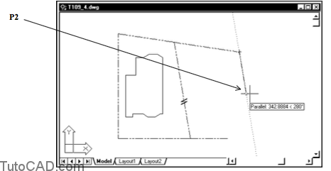
- Type 492 inches (41 feet) & press <enter> to use this as the direct distance entry when the Parallel tooltip is displayed.
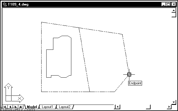
- Invoke the Endpoint osnap shown below then left-click to use this as the second point of the LINE and press <enter> to terminate Line.
- Pick Format + Point Style and select the style shown below. Then pick OK.
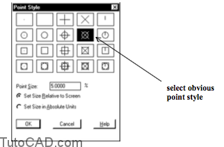
In the next step you will place a survey marker symbol using a POINT object and you will want it to be an obvious style.
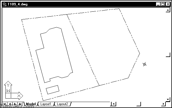
- the survey marker should be aligned along the parallel LINE and it should be at a distance of 120 inches (10 feet) past the corner.
- you will use the Extension osnap tool, tracking and direct distance entry to place this survey marker precisely.
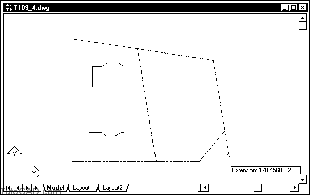
- Pick Draw + Point + Single Point. Invoke the Endpoint osnap tooltip and acquire this point as a tracking point.
- Move your crosshairs to track along the Extension direction. Type 120 and press <enter> when you see the Extension tooltip.
- Pick Tools + New UCS + World to restore the WCS.
- Pick View + 3D Views + Top to align the current view with the WCS.
- Make FOUNDATION the current Layer.
- Use the Line command to draw the rectangular garden plot that is 60 inches by 120 inches. This rectangle should be aligned with the left outside wall and be 60 inches from the lower left corner of the house. Use Parallel & Extension osnaps and tracking techniques to draw this rectangle using one Line command.
- Save the changes to this drawing and Close the file.