How to use Ordinate Dimensions
Here is how to use Ordinate Dimensions in AutoCAD
Ordinate dimensions can be used as an alternative to linear dimensions (often used to dimension CNC machined parts).
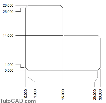
- X ordinates are labeled along the top or bottom
- Y ordinates are labeled along the left or right side.
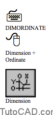
- create this type of dimension using Dimordinate.
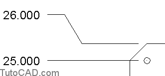
Leader lines can be straight or “dog legged” to clear obstructions in the drawing if required
- or to spread out dimensions that would be too close together if the leader lines were straight.
Ordinate dimensions are relative to the current UCS at the time the dimension is created.
- use the Origin option of the Ucs command to define a UCS at the desired location before creating ordinate dimensions.
Practice : ordinate dimensions tutorial in AutoCAD
- Close the drawing from the previous exercise if it is open.
- Open the T112_2.dwg drawing in your personal folder.
- Pick Tools + New UCS + Origin. Press & hold the <shift> key while you right-click in the drawing area to invoke a shortcut and select Intersection. Invoke the Extended Intersection tooltip shown near P1 and left-click to continue. Invoke the Intersection osnap shown near P2 then left-click to move the UCS origin to the intersection osnap marker shown.
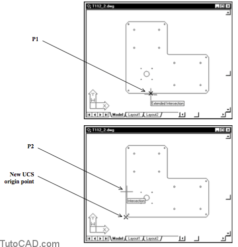
When you explicitly invoke the Intersection osnap as an override you can pick 2 LINEs to use the point of intersection of these LINEs.
– these LINEs do not have to actually cross or meet.
4- Left-click on the POLAR status bar button to turn this tool On (if it is Off).
5- Pick Dimension + Ordinate. Invoke the Endpoint osnap near P1 then left-click to use this point as the feature location. Move your crosshairs to the left and left-click near P2 when the tooltip angle is 180 degrees to use this as the leader endpoint. The command line history is shown.
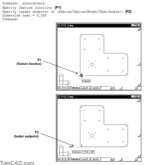
The POLAR tool was On but the Extension osnap may also constrain your leader line endpoint to be in a 180 degree direction.
– if you want straight leader lines you should pick leader line endpoints using orthogonal angles (0, 90, 180 or 270 degrees)
You can use the Dimcontinue command after you create an Ordinate dimension to continue adding ordinate dimensions.
- -this is much faster than repeatedly using multiple Dimordinate commands to achieve the same results.
- -you can also press <enter> at the first Dimcontinue prompt to select the desired Ordinate dimension to continue from.
- -ordinate dimensions will be aligned with the selected (or last) dimension when you use this Dimcontinue approach.
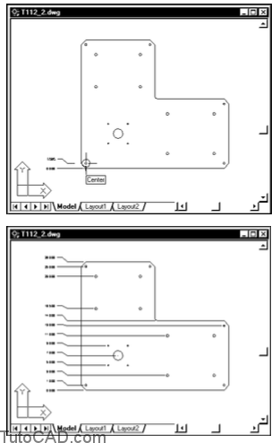
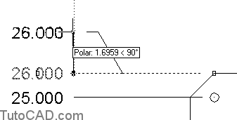
6- Pick Dimension + Continue. Invoke the Center osnap shown below and left-click to use this as the feature location point. Use a similar technique to create dimensions for the other CIRCLE centers (Center osnaps) and part edges (Endpoint osnap) shown below. Press <enter> twice to terminate Dimcontinue when you are finished creating these dimensions.
More practice
7- Use a similar approach to create the X ordinate dimensions along the bottom of the part as shown.

8- Save this drawing and Close the file.
You imply which ordinate (X or Y) is dimensioned by where you
pick for the leader endpoint.
– but you can also right-click to select either the Xdatum or Ydatum directions from a shortcut if you prefer.
You can use grip editing techniques to create dog legged leaders (from straight leaders) or add extra space if required.
-select the desired ordinate dimension when no command is running & left-click on the leader endpoint grip to make it hot.
-pick a new location for the leader endpoint.
press <Esc> twice to clear the grips.