AutoCAD – the FILLET command. As designers, engineers, or CAD enthusiasts, we constantly look for ways to make our design process smoother, and understanding the functionalities of such commands is crucial. This command allows us to create rounded corners, thereby giving our designs a more refined and professional look. But there’s much more to the FILLET command than just creating rounded edges. This guide provides a deep dive into the command, its applications, its different modes and options, and the reasons for its use. And for those who are looking for quick answers to specific questions, we have a FAQ section that covers 25 common questions related to the FILLET command.
Overview
The FILLET command in AutoCAD is a powerful tool that facilitates drawing and designing by creating a round corner or arc between two lines that meet at a point (also known as a vertex). By using the FILLET command, you can easily create smooth transitions between lines, arcs, and polylines, enhancing your design’s overall appearance and functionality.
Detailed Description
The FILLET command works by creating a tangent arc between two objects and then trims or extends the objects to meet the arc. The radius of the arc is determined by the ‘radius’ value, which can be set prior to activating the command.
Different Modes and Options
There are several options associated with the FILLET command that adjust its functionality:
- Radius: This option allows you to specify the radius of the fillet arc. The command
FILLET>RADIUScan be used to set this value. - Trim: The trim option, when enabled, trims the lines to the fillet. If the trim option is off, the command will create the fillet but leave the original lines intact, extending beyond the fillet.
- Multiple: This option allows you to select multiple pairs of objects to fillet at once.
- Polyline: This option allows you to select a polyline to fillet all its vertices.
Reasons for Use
The FILLET command is used for various purposes such as:
- Enhancing aesthetic appeal by creating smooth corners in designs.
- Simplifying complex designs by creating a round intersection between two lines or curves.
- Increasing efficiency by allowing the filleting of multiple lines or curves at once.
Accessing the FILLET Command
The FILLET command can be accessed in several ways:
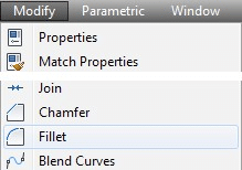
Menu: Modify > Fillet
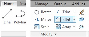
Ribbon: Home tab > Modify panel > Fillet
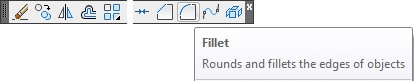
Toolbar: Modify toolbar > Fillet
Command Bar: Type FILLET or F and press Enter.
Shortcut: The keyboard shortcut is F.
How to Use the FILLET Command: Step-by-Step
Here’s a step-by-step guide on how to use the FILLET command:
- Step 1: Select the
FILLETcommand using one of the methods above. - Step 2: Enter the radius of the fillet by typing
Rin the command bar, then enter the radius value and press Enter. - Step 3: Select the first object you want to fillet.
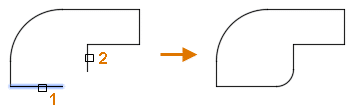
- Step 4: Select the second object.
The fillet, an arc with the specified radius, will then be created between the two objects.
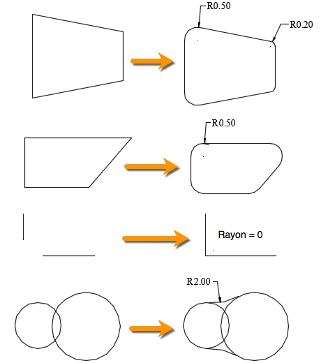
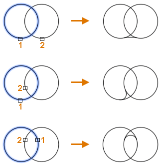
Example 1 :
Example 2 :
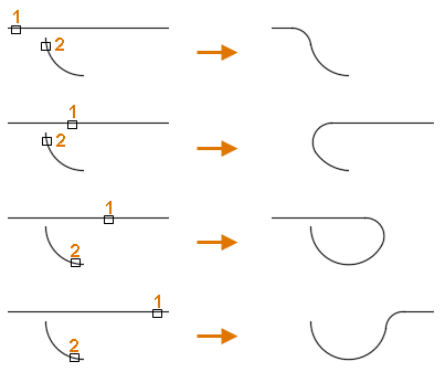 Example 3:
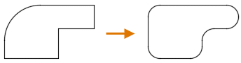
Example 4 (Polyline):
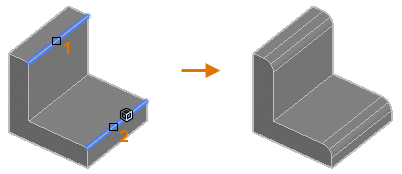
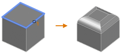
Example 5 (Edges of a 3D solid) :
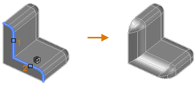
Example 6 (An edge along the side of a 3D solid) :
Example 7 (Edges on the face of a 3D solid or surface) :
Youtube FILLET command Tutorials
Related AutoCAD Commands
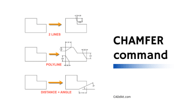
- CHAMFER: This command is used to create a beveled corner between two lines, much like
FILLET, but with a straight line instead of an arc. - BLEND: This command creates a spline in the gap between two selected lines or curves.
- OFFSET: This command creates parallel or concentric copies of lines, polylines, circles, arcs, or splines.
Remember, mastering these commands will allow you to work more efficiently and effectively within AutoCAD. Happy designing!
Frequently Asked Questions about the FILLET Command in AutoCAD
1. Can I create a fillet with zero radius?
Yes, you certainly can. A fillet with a zero radius essentially connects two lines with another straight line, effectively creating a ‘bevel’ rather than a ’round’. This can be useful when you want to create a sharp transition between two lines. To do this, you would set the radius to zero before using the FILLET command.
2. Can the FILLET command be used on 3D objects?
The FILLET command is primarily designed for use with 2D objects. However, AutoCAD does offer a FILLETEDGE command that applies a similar concept to the edges of 3D solids. This command works much like the 2D FILLET command, but with an additional dimension to consider.
3. Is it possible to fillet all corners of a polyline at once?
Yes, it’s possible. By using the Polyline option in the FILLET command, you can fillet all corners of a polyline at once. This can be a great time saver when working with complex polylines with many vertices.
4. What happens if the selected lines for the FILLET command don’t intersect?
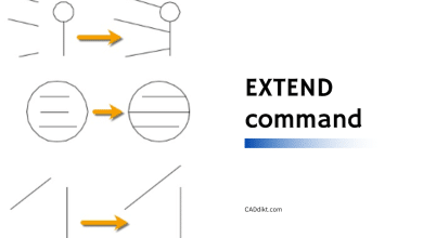
If the lines you’re trying to fillet don’t intersect, AutoCAD will extend them so they do intersect, and then apply the fillet. This is subject to the ‘trim’ mode being enabled. If ‘trim’ mode is off, the fillet will be created at the theoretical intersection point, with the original lines remaining unchanged.
5. What’s the difference between the FILLET and CHAMFER commands?
While both commands are used to create transitions between two lines, they do so in different ways. The FILLET command creates a rounded corner, while the CHAMFER command creates a beveled corner. The choice between the two usually depends on the specific design requirement.
6. Can I use the FILLET command on arcs or circles?
Yes, you can use the FILLET command on arcs and circles. The command will create a tangent arc between the two selected objects, and trim or extend them as necessary to meet the arc.
7. What is the ‘Multiple’ option in the FILLET command?
The ‘Multiple’ option allows you to apply the FILLET command to multiple pairs of objects without having to reselect the command each time. This can be a significant time-saver when you need to apply the same fillet radius to multiple pairs of lines or curves.
8. How can I undo a FILLET operation?
You can undo a FILLET operation like any other command in AutoCAD by using the UNDO command or the Ctrl+Z shortcut. This will revert the drawing to the state prior to the FILLET command being applied.
9. Can I fillet non-parallel lines?
Yes, non-parallel lines can be filleted. The FILLET command will create an arc at the point where the lines would theoretically intersect if extended, and then trim the lines to the arc.
10. How can I modify an existing fillet?
To modify an existing fillet, you can use the FILLET command again with a different radius and reapply it to the same lines. Alternatively, you can use the EXPLODE command to break the fillet into separate entities, modify them as needed, and then recreate the fillet.
There could be a few reasons why you’re having trouble creating a fillet between two lines. The lines may not intersect, even if extended, or the specified fillet radius might be too large for the selected lines. Adjusting the fillet radius or the position/orientation of the lines might solve this issue.
12. Is the FILLET command affected by the current layer?
The FILLET command does not consider the current layer when creating a fillet. The created fillet will maintain the properties of the objects being filleted. If the two objects are on different layers, the resultant fillet will adopt the properties of the first object selected.
13. How can I use the FILLET command to round all corners of a rectangle?
You can easily round all corners of a rectangle by using the Polyline option of the FILLET command. First, convert the rectangle into a polyline, if it’s not already one. Then, use the FILLET command, select the Polyline option, and select the polyline rectangle.
14. What does ‘Trim mode’ mean in the FILLET command?
Trim mode in the FILLET command determines whether or not the lines or curves to be filleted are trimmed to meet the fillet. If trim mode is on, the lines are trimmed; if it’s off, the lines are extended to the theoretical intersection point, while the original lines remain unchanged.
15. Can I use different radii for different corners in the same polyline?
Yes, you can use different radii for different corners in the same polyline. After creating the polyline, use the FILLET command, set the desired radius, and then select the two segments forming the corner you want to fillet. Repeat the process for each corner with the desired radius.
16. Can the FILLET command be used on splines?
Yes, the FILLET command can be used on splines, but with some limitations. The command will create an arc that is tangent to the selected points on the spline. However, keep in mind that the results may not always be as expected due to the complex nature of splines.
17. How can I create a fillet between two parallel lines?
To create a fillet between two parallel lines, you first need to create an intersection point. This can be done by drawing a line between the two parallel lines. Then you can use the FILLET command to create a fillet at the intersection of the new line and one of the parallel lines.
18. What’s the difference between the FILLET and BLEND commands?
While both commands create a transition between two objects, they do so in different ways. The FILLET command creates a tangent arc between two objects, whereas the BLEND command creates a spline that smoothly transitions between the two objects.
19. Can the FILLET command be used on ellipses?
The FILLET command does not work directly on ellipses as it does on lines, arcs, or circles. To create a fillet effect on an ellipse, you would have to convert the ellipse into a polyline or spline first.
20. How can I create a fillet with a variable radius?
AutoCAD does not directly support creating a fillet with a variable radius using the FILLET command. However, you can achieve a similar effect by creating a spline or a series of fillets with different radii.
Yes, the FILLET command in AutoCAD provides a preview before the command is finalized. After setting the radius and selecting the objects to be filleted, a preview of the fillet is displayed, allowing you to adjust the radius or the objects selected before finalizing the command.
22. Can I save my preferred fillet radius as a default setting?
AutoCAD doesn’t offer a specific setting to save the default radius for the FILLET command. However, the software does remember the last used radius within the same session. If you consistently use the same radius, you can create a script or a custom command to set the fillet radius when you start a new drawing session.
23. How can I use the FILLET command to create a sharp corner?
To create a sharp corner using the FILLET command, you would set the radius to zero. This will connect the two lines with another straight line, forming a sharp corner instead of a rounded one.
24. Can I use the FILLET command with blocks?
While you can’t directly fillet the elements of a block using the FILLET command, you can first explode the block into its constituent elements, apply the fillet, and then create a new block if needed.
25. Is the FILLET command available in AutoCAD LT?
Yes, the FILLET command is available in AutoCAD LT. The command works the same way as in the full version of AutoCAD, offering the same options and capabilities.
Conclusion
We’ve now reached the end of our journey exploring the FILLET command in AutoCAD. We’ve examined the command in depth, discussed its various modes and options, and answered some of the most frequently asked questions about its use. The FILLET command, with its ability to create smooth transitions and enhance the aesthetic appeal of our designs, is indeed an essential tool in our CAD toolbox. Whether you’re a seasoned professional or a beginner in AutoCAD, we hope this guide has provided you with valuable insights and will serve as a handy reference in your future design projects. Remember, the more you use and experiment with these commands, the more comfortable you’ll become. So keep designing, keep exploring, and let your creativity flow.