AutoCAD, a robust drafting software, is extensively utilized in a multitude of sectors for creating detailed 2D and 3D drawings. One of the key features of this software lies in its ability to create and manage POLYLINEs and REGIONs. POLYLINEs and REGIONs are elementary yet essential tools that help designers in creating complex structures with relative ease. In this article, we delve into how to create, modify, and utilize POLYLINEs and REGIONs in AutoCAD, along with understanding their significant benefits.
How to create POLYLINEs & REGIONs in AutoCAD
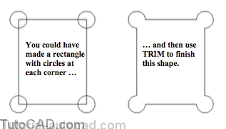
One way to create a LWPOLYLINE is to use the Pline command but this approach can be tedious for complex shapes.
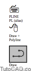
- Pline (an abbreviation for PolyLINE) is used to create single objects that can be made up of multiple LINE & ARC segments.
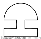
- as an example, the shape below could be made from 9 individual LINEs & one ARC or it could be made from one LWPOLYLINE.
Prior to AutoCAD Release 14 the Pline command created POLYLINE objects but now these objects are Light Weight (LW)
- LW signifies that the method for storing polyline data requires less space (to be managed more efficiently by AutoCAD).
LWPOLYLINEs can require more effort to create & edit compared to using Line or Arc commands to make individual LINEs & ARCs.
- if you do not require the special properties of LWPOLYLINEs then you should probably use individual LINEs or ARCs instead.
LWPOLYLINEs offer the following benefits
- you can select an entire shape by selecting only one segment (which makes it easier to Copy, Move, etc…)
- you can use Region to convert LWPOLYLINEs into REGION objects to perform an analysis (area, perimeter, centroid, etc.)
- each LWPOLYLINE segment can have a different Width (the width of other 2D objects is controlled with Lineweight instead).
- you can perform 3D operations on LWPOLYLINEs which makes them very important objects if you plan to work in 3D.
Sometimes it is easier to create a LWPOLYLINE by first creating the desired shape with individual LINEs or ARCs using Line & Arc
- then use the Pedit command to Convert and then Join the individual segments into a single LWPOLYLINE object.
- you can take advantage of LWPOLYLINE features without having to master the Pline command.
Each segment must end precisely where the next segment begins or you will not be able to Join segments using Pedit
- so you should use Endpoint osnaps if you create individual LINE & ARC objects to create LWPOLYLINEs using Pedit.
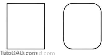
You can use the Rectang command to quickly create closed LWPOLYLINE objects that are rectangular in shape.
- you are prompted for two corner points and you can also specify a fillet radius to use in each corner.
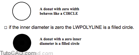
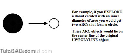
The Donut command creates circular LWPOLYLINEs & you can specify the width of these objects using inner & outer diameters.
- if inner & outer diameters are the same then width is zero
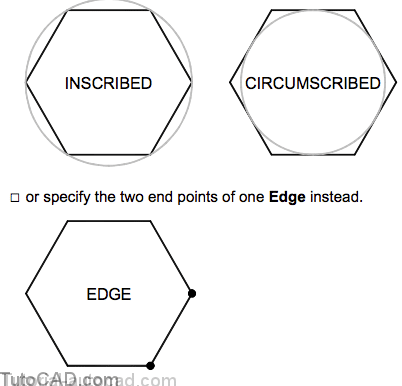
You can use Polygon to create LWPOLYLINEs that form a perfect polygon shape (of equal length segments) with up to 256 sides.
- specify the radius & center of a circle that the polygon would be either inscribed in or circumscribed about
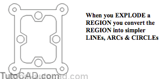
Any LWPOLYLINE can be converted to individual LINE or ARC segments with the Explode command.
- all width information would be lost because LINE & ARC objects do NOT have width (only Lineweight for plotting purposes).
REGIONS are enclosed 2D areas that you can create with the Region command by selecting closed shapes called loops.
- a loop is a curve or a sequence of connected curves that defines an area on a plane with a boundary that does not intersect itself.
Objects used for a loop must either be closed or form closed areas by sharing endpoints with other objects.
- loop shapes can be modeled from LINEs, LWPOLYLINEs, CIRCLEs, ARCs, ELLIPSEs & SPLINEs (& other 2D objects).
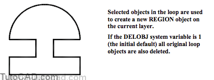
For example, the shape illustrated below could be selected as a loop when you create a new REGION object with the Region command.
- this loop shape could be modeled using individual LINEs and one ARC or it could be one single LWPOLYLINE object.
- you can select objects for more than one loop to create multiple REGION objects in the same Region command.
- AutoCAD reports the number of loops extracted and the number of REGIONs created at the end of the Region command.
- all loop objects in the same Region command must be coplanar.
Command: REGION↵
Select objects: (select objects for the desired loop)
Select objects: ↵
1 loop extracted.
1 Region created.
Command:
Why Create REGIONs?
REGIONs have more intelligence than other 2D drafting objects.
- you can use boolean operations on REGIONs for a more efficient & intuitive construction method to draw complex shapes.
- you can select a REGION as a boundary object to HATCH.
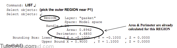
- you can analyze a REGION to find useful information about a boundary such as the area, perimeter & center of gravity.
- 2D REGIONs can be used to generate complex 3DSOLIDs.
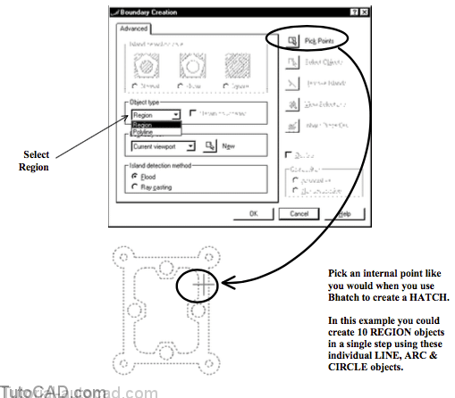
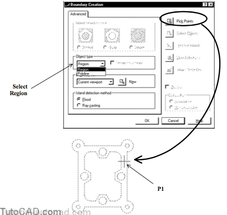
The easiest way to make REGIONs is with the Boundary command (this is like automatically finding HATCH boundaries using Bhatch).
- select Region as the Object type (initial default is Polyline).
- then pick the Pick Points button and pick an internal point to let AutoCAD generate appropriate boundaries for new REGIONs.
- AutoCAD creates an outer REGION along with a separate REGION for every internal island that it detects.
Command: BOUNDARY↵
(pick the “Pick Point” button in the dialogue box)
Select internal point: (pick an internal point)
Selecting everything…
Selecting everything visible…
Analyzing the selected data…
Analyzing internal islands…
Select internal point: ↵
10 loops extracted.
10 Regions created.
BOUNDARY created 10 regions
Command:
You can use boolean operations to combine several REGIONs (in the same plane) into a single REGION.
- you will practice making a complex 2D shape from simpler shapes using these operations.
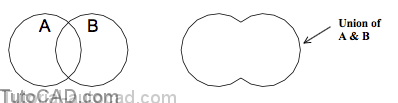
Use Union to create a new REGION that includes the combined areas of the selected REGIONs.
- you are prompted to select REGIONs (or SOLIDs) to join together and you can pick as many objects as you wish.
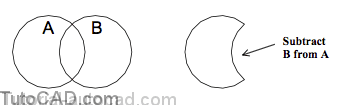
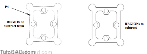
Use Subtract to remove the areas of selected REGIONs from another larger REGION.
- this is a two part command in which you are first prompted to select REGIONs (or SOLIDs) that you will subtract from.
- then you are prompted to select the REGIONs (or SOLIDs) that you would like to subtract.
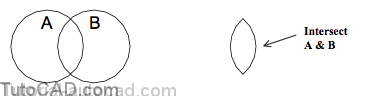
Use Intersect to generate a new REGION that includes only the areas that all of the other selected REGIONs have in common.
PRACTICE CREATING LWPOLYLINES & REGIONS
»1) Close the drawing from the previous exercise if it is open.
»2) Open the T208_5.dwg drawing in your personal folder.
»3) Pick Modify + Polyline. Select the vertical LINE near P1. AutoCAD will tell you that it is not a polyline and ask you if you want to turn it into one. Press <enter> to accept <Y>. Enter J to use the Join option. Enter ALL to select all objects in the drawing then press <enter> to continue. Then press <enter> to complete the Pedit command.
Command: PEDIT↵
Select polyline: (pick the vertical LINE near P1)
Object selected is not a polyline
Do you want to turn it into one? <Y> ↵
Enter an option [Close/Join/Width/Edit vertex/Fit/Spline/Decurve/Ltypegen/Undo]: J ↵
Select objects: ALL↵
40 found
Select objects: ↵
7 segments added to polyline
Enter an option [Open/Join/Width/Edit vertex/Fit/Spline/Decurve/Ltype gen/Undo]: ↵
Command:
4) Pick Tools + Inquiry + Area. Enter 0 to invoke the Object option then enter L to select the Last (LWPOYLINE) object.
Command: AREA↵Specify first corner point or [Object/Add/Subtract]: O ↵
Select objects: L↵
Area = 0.8942, Perimeter = 4.6850
Command:
The Area command finds the area and perimeter of a closed LWPOYLINE which can be practical design data to extract.
5) Pick Tools + Inquiry + List and select the new LWPOLYLINE near P1. Press <enter> to read the report. Press <enter> to continue until you see the Command: prompt. Press F2 to return to the graphic window.
This outer shape is now one LWPOLYLINE object and this new object replaced the original LINE and ARC objects.
- you selected ALL objects to Join to the selected LINE object in step 3 but only 7 of the 40 objects shared appropriate end points.
- now you can work with this outer shape more efficiently because it is a single object (a LWPOLYLINE).
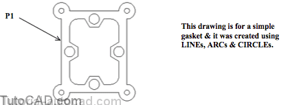
It would have been complicated to create this outline shape for the gasket directly as a LWPOLYLINE using only the Pline command.
- you would have had to switch back and forth between Line and Arc modes and the arc directions would have been difficult.
- whereas, using Pedit to Join existing LINE and ARC segments is easy if these objects already exist and meet end to end.
- the outer shape could have been easily created using the method described below.
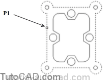
6) Pick Draw + Boundary. Select Region as the Object type then pick the Pick Points button. Pick the internal point inside the gasket near P1 then press <enter> to complete the Boundary command.
Command: BOUNDARY↵
(pick the “Pick Point” button in the dialogue box) Select internal point: (pick an internal point) Selecting everything…
Selecting everything visible…
Analyzing the selected data…
Analyzing internal islands…
Select internal point: ↵
10 loops extracted.
10 Regions created.
BOUNDARY created 10 regions
Command:
You just used the new LWPOLYINE object & the other LINEs, ARCs and CIRCLEs to generate 10 new REGION objects.
- using the Boundary command is like using the Bhatch command except a HATCH object is not created.
7) Pick Tools + Inquiry + List. Select the new REGION object near P1 and press <enter> to read the report. Press F2 to return to the graphic window.
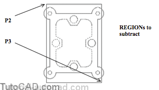
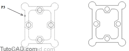
8) Pick Modify + Solids Editing + Subtract. Pick the outer REGION near P1 as the region to subtract from and press <enter> to continue.
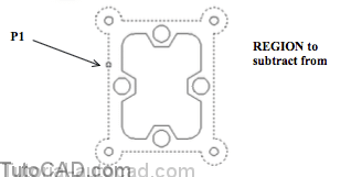
9) Hold your cursor near P2 so it is not above any objects and left-click to invoke an implied window. Then left-click near P3 to select the 9 REGION objects inside the outer REGION as the objects to subtract. Press <enter> to complete the Subtract command.
When you work with REGIONs that have holes (islands) in them you can change the Shademode to visualize the holes better.
10) Pick View + Shade + Flat Shaded.

11) Pick Tools + Inquiry + Mass Properties. Enter L to select the Last object then press <enter> to read the report. Press <enter> again to complete the command.
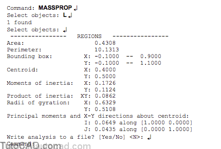
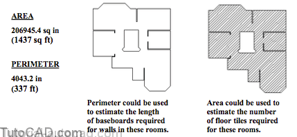
You can use the Massprop command to find the area, perimeter and centroid of complex REGIONs.
- in this example, the perimeter could be an important design consideration when designing a punch to cut out the gasket.
- the area could be used to compute the part volume for various different gasket thicknesses.
Some of the other properties (e.g. Moments of inertia) are relative to the origin of the current UCS
- you can move the UCS to an appropriate location before invoking the Massprop command.
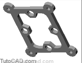
12) Pick Draw + Solids + Extrude. Enter L to select the Last object then press <enter> to continue. Enter 0.060 as the height and press <enter> to use 0 for the draft angle.
13) Pick View + 3D Orbit. Right-click in the drawing area to invoke a shortcut and pick More + Continuous Orbit. Click near the center of your screen then drag your cursor slowly in any direction. When you release your mouse button the 3DSOLID will revolve continuously around your screen.
» 14) Pick View + 3D Views + Top.
» 15) Pick View + Shade + 2D Wireframe.
» 16) Save the changes to your drawing.
You used the Boundary command to generate REGION objects from closed shapes in a completed 2D drawing.
- you used Subtract to create a complex REGION (with holes in it) and this let you compute the area & perimeter for the part.
- then you used Extrude to convert the REGION into a 3DSOLID.
If you complete the next more practice exercise you can use a different approach to create these objects from scratch.
- this approach is a powerful construction method for 2D shapes.
More practice?
» 17) Pick Modify + Erase. Enter ALL to select all objects in the drawing then press <enter> to delete all objects.
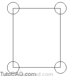
» 18) Pick Draw + Rectangle. Pick any point in the lower left corner of the screen and enter @0.8,1.0 as the other corner.
» 19) Pick Draw + Circle + Center,Radius. Use Intersection osnaps at each corner for the center point and a radius of 0.1 to create the 4 CIRCLEs shown.
20) Pick Draw + Region. Enter ALL to convert the rectangle (a LWPOLYLINE) and the CIRCLEs to 4 separate REGIONs. Press <enter> to complete the command.
21) Pick Modify + Solids Editing + Union. Enter ALL to union all 5 REGIONs into a single REGION object. Press <enter> to complete the command.
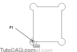
22) Pick Draw + Rectangle. Enter F to use the Fillet option and enter 0.1 as the new fillet radius. Then invoke a Center osnap near P1 as the first corner then enter @0.6,0.8 as the other corner for the rectangle.
Command: RECTANG↵
Specify first corner point or [Chamfer/Elevation/Fillet/Thickness/Width]: F ↵Specify fillet radius for rectangles <0.0000>: 0.1 ↵
Specify first corner point or [Chamfer/Elevation/Fillet/Thickness/Width]: (P1 Center) Specify other corner point: @0.6,0.8 ↵
Command:
23) Pick Modify + Move. Enter L to select the Last object then press <enter> to continue. Enter 0.1,0.1 as the displacement & press <enter> at prompt for the 2nd point of displacement.
24) Pick Draw + Region. Enter L to select the Last LWPOLYLINE object then press <enter>.
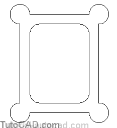
25) Pick Modify + Solids Editing + Subtract. Select the outer REGION as the object to subtract from and press <enter> to continue. Then select the inner REGION as the object to subtract and press <enter> to complete the command.
26) Pick View + Shade + Flat Shaded to verify that you have created the REGION illustrated below. Then pick View + Shade + 2D Wireframe to return to this mode.
27) Right-click on the OSNAP status bar button to invoke a shortcut and select Settings. Check Midpoint and pick OK.
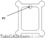
28) Pick Draw + Circle + Center,Diameter. Use a Midpoint osnap near P1 for the center & enter a diameter of 0.125.
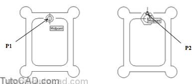
29) Pick Draw + Polygon. Enter 6 as the number of sides. Use a Center or Midpoint osnap near P1 for the center. Enter C to use the Circumscribed method. Use a Midpoint osnap near P2 for the radius.
Command: POLYGON↵
Enter number of sides <4>: 6 ↵
Specify center of polygon or [Edge]: (use Midpoint or Center osnap near P1)
Enter an option [Inscribed in circle/Circumscribed about circle] <C>: C ↵
Specify radius of circle: (use Midpoint osnap near P2)
Command:
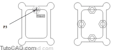
30) Pick Draw + Region and select the new LWPOLYLINE (the polygon you just created) and the CIRCLE then press <enter> to complete Region.
31) Pick Modify + Copy. Select the two new REGIONs that you created in the last step and press <enter> to continue. Right-click in the drawing area to invoke a shortcut and pick Multiple. Use a Center or Midpoint osnap near P3 as the base point. Then use Midpoint osnaps for the second points of displacement to copy these REGIONs onto each side of the gasket as shown below. Press <enter> to complete the Copy command.
In the next step you will Rotate the hexagonal REGIONs on the vertical edges by 90 degrees so they are aligned with these sides.
32) Pick Modify + Rotate and select the hexagonal REGION near P1 and press <enter> to continue. Use a Midpoint osnap near P1 for the base point and enter 90 as the rotation angle. Repeat for the other hexagonal REGION near P2.
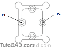
33) Pick Modify + Solids Editing + Union. Select the outer REGION near P3 and select the 4 hexagonal REGIONs then press <enter> to complete the command.
34) Pick Modify + Solids Editing + Subtract. Select the outer REGION near P4 as the object to subtract from then press <enter> to continue. Then select the 4 circular REGIONs as the objects to subtract & press <enter> to complete the Subtract command.
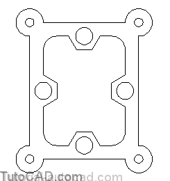
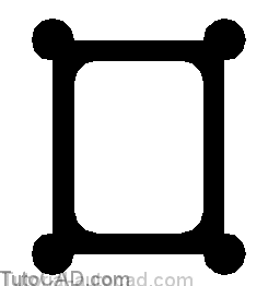
35) Complete this gasket model by subtracting circular REGIONs in the corner of the gasket. Each of the 4 new holes should have a diameter of 0.0625 and be centered in the corner as shown. Verify that the final REGION has the holes as shown by changing the Shademode to Flat Shaded.

36) Pick Modify + Explode and select the new REGION. Press <enter> to continue.
37) Save the changes to the drawing & Close the file.
Still more practice?
38) Open the T208_6.dwg drawing in your personal folder. Create a single REGION that corresponds to the hatched area shown below. Find the corresponding area and perimeter of this REGION. This drawing is in inches.
FAQ
1. How to create POLYLINEs in AutoCAD?
Firstly, to create a POLYLINE in AutoCAD, open your AutoCAD software and choose the ‘Draw’ toolbar. From the toolbar, select the ‘Polyline’ tool, symbolized with a line bent into two parts. This activates the POLYLINE command, allowing you to start drawing a polyline.
In the second step, you click on the workspace where you want to start your polyline. Each subsequent click adds another vertex to the polyline, and a line segment is drawn between each pair of vertices. You can continue to click to add as many vertices as you want.
Finally, to finish the polyline, either press ‘Enter’ on your keyboard or right-click and select ‘Enter’ from the context menu. This action will complete the polyline. It’s important to remember that the POLYLINE command creates a single, continuous object, even if it contains multiple straight or curved segments.
2. How to modify POLYLINEs in AutoCAD?
Modifying polylines in AutoCAD involves several steps. Firstly, you can select the polyline you want to modify and right-click to open the context menu. Choose the ‘Properties’ option. This will open a properties window where you can modify characteristics such as color, line weight, and line type.
Next, to edit the vertices of a polyline, you can use the ‘PEDIT’ command. Once you start this command and select the polyline, you will have several options including moving, adding, or deleting vertices, converting the polyline into a different shape, joining multiple polylines together, or changing the width of the polyline.
Lastly, you can use grips to modify the shape of the polyline directly. When you select a polyline, small squares called grips appear at each vertex. You can click and drag these grips to move the vertices around, changing the shape of the polyline.
3. What are the benefits of using POLYLINEs in AutoCAD?
Using POLYLINEs in AutoCAD has several benefits. Firstly, since a polyline is treated as a single object, you can easily move, copy, or delete the entire shape without having to select multiple individual lines. This can be a great time-saver, particularly in complex drawings.
Next, polylines can include straight lines, arcs, or a combination of both, making them very versatile. You can change the width of a polyline, giving you more control over its appearance than simple lines or arcs.
Finally, polylines are essential for creating regions, hatches, and boundaries. The software treats a closed polyline as a single enclosed space, which can be filled with a hatch pattern or converted into a region. This allows you to calculate areas and perimeters, or to create solid filled shapes.
4. How to create REGIONs in AutoCAD?
Creating REGIONs in AutoCAD is straightforward. Firstly, you need to create a closed shape using polylines, circles, ellipses, or other closed shapes. Remember that the shape must be closed without any gaps between the endpoints of the lines or arcs.
Secondly, once your closed shape is ready, go to the ‘Draw’ toolbar and select ‘Region’. This command prompts you to select objects to turn into regions. Select your closed shape, and AutoCAD will create a region from it.
Finally, your shape is now a region. This is a single object, which can be manipulated as one piece. You can use this to calculate area and perimeter, to create solid filled shapes, or for Boolean operations with other regions.
5. How to modify REGIONs in AutoCAD?
To modify regions in AutoCAD, you can use Boolean operations. Firstly, if you have two regions, you can use the UNION command to merge them into a single region. This is useful if you want to create a complex shape from two simpler ones.
Secondly, you can use the SUBTRACT command to remove one region from another. This command asks you to select the regions in the order you want to subtract them. The first region you select will be the one from which the second region will be subtracted.
Lastly, the INTERSECT command can be used to create a new region from the overlapping areas of two existing regions. This can be useful if you want to highlight the common area between two shapes.
6. What are the benefits of using REGIONs in AutoCAD?
The use of REGIONs in AutoCAD has several benefits. Firstly, regions allow you to calculate the area and perimeter of complex shapes easily. This can be useful in many fields, such as architecture and engineering, where accurate measurements are vital.
Secondly, regions can be used in Boolean operations, allowing you to combine, subtract, or find the intersection of shapes. This can be a powerful tool for creating complex designs from simpler shapes.
Finally, regions are treated as single objects, like polylines, which makes it easier to manipulate them. You can move, copy, delete, or scale a region as a single object, which can simplify the process of editing your drawing.
7. Can I convert a POLYLINE to a REGION and vice versa in AutoCAD?
Converting a POLYLINE to a REGION in AutoCAD is quite straightforward. You need to make sure your polyline forms a closed shape, then use the ‘Region’ command to convert it. Select the polyline when prompted to select objects, and AutoCAD will create a region from your polyline.
However, converting a region back into a polyline is not as straightforward. While there’s no direct ‘convert to polyline’ command for regions, you can recreate the region boundary as a polyline manually. This involves tracing over the region using the POLYLINE command.
Remember, when you convert a POLYLINE to a REGION, the region acts as a single object with no vertices, unlike polylines. This means that when you need to edit the shape in detail, using a POLYLINE might be more suitable than a REGION.
Conclusion
Mastering POLYLINEs and REGIONs in AutoCAD can significantly augment your CAD proficiency. These features not only simplify the process of designing complex structures, but also help in the precise calculation of areas and perimeters, thereby assisting in effective project planning and execution. As we continue to explore and harness the full potential of AutoCAD, it becomes clear that these foundational tools, when utilized correctly, can transform the way we approach design and drafting challenges. With practice and patience, the creative possibilities are virtually limitless.