How to create LINE Objects
Here is how to use Line command in AutoCAD
One Line command can be used to draw a 2D shape comprised of many straight-edged segments.
- even if segments are created in the same Line command it is important to realize that each segment is a separate object.
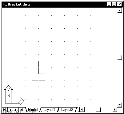
For example, the following simple 2D drawing would require 16 separate LINE objects to model the three views for this bracket
- but you could create all of these 16 LINE objects using 5 (or more) separate Line commands.

You have already been using the Line command to create LINE objects when you practiced different ways to supply points.
- you may already know enough about LINEs for your needs. Three features of the Line command can make it easier for you to work with LINEs.
these features include Continue, Close & Undo
In the next exercise you will learn how to
- use the Continue feature to begin your next Line command where your last LINE segment ended.
- use Close to draw the next segment back to the starting point of the current Line command.
- use Undo in the current Line command (without having to start all over again) when you supply the wrong points by mistake.
MORE PRACTICE CREATING LINEs in AutoCAD
1)Launch AutoCAD (if it is not already running). Close all open drawings (if there are drawings open). If AutoCAD was running already then pick File + New to continue.
First, you will start this drawing from scratch using default settings for Metric drawings.
Next, you will adjust the drawing LIMITS for an A4 size sheet at a 2:1 drawing scale.
Then you will create the outline for this simple bracket using LINE objects.
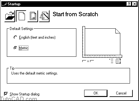
2) Select the Start from Scratch button. Select Metric as the Default Settings and then pick OK to create a new drawing.
You have adjusted many system variables to be appropriate for drawing units to represent millimeters.
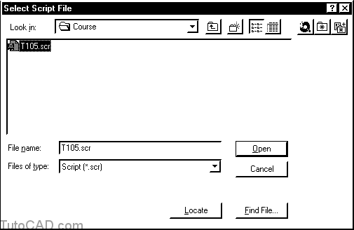
3) Pick Tools + Run Script. Select your personal folder to Look in and select T105.scr as the script File name. Then pick the Open button to run this script.
There are many different system variables that control coordinate input and drafting tools in AutoCAD 2000.
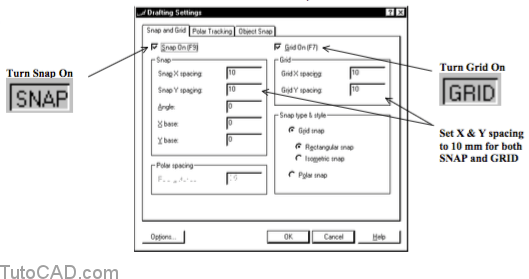
- the script you ran in the last step will ensure that your system is set up to match the behavior described in the exercises.4) Right-click on the GRID button in the status bar to invoke a shortcut and select Settings. Now check both Snap On and Grid On and make sure the X & Y Spacing for Snap & Grid are all set to 10. Then pick OK.
5) Pick Format + Drawing Limits and follow the dialogue below to adjust the drawing limits on the Model tab for an A4 sheet (210×297 mm) for a 2:1 drawing scale.
Command: ‘_limits
Reset Model space limits:
Specify lower left corner or [ON/OFF] <0.0000,0.0000>: ↵
Specify upper right corner <420.0000,297.0000>: 105,150 ↵
Command:
6)Pick View + Zoom + All.

The size of the new drawing Limits is now 105 x 150 mm
- when you Plot this area at a plot scale (drawing scale) of 2:1 the objects will be twice their actual size on the plot.
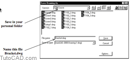
- so this area would be 210 x 300 mm ( 2*105 x 2*150 ) which is approximately the same size as an A4 sheet.7) Pick File + Save. Enter Bracket.dwg as the drawing File name and select your personal folder as the Save in location. Then pick the Save button.
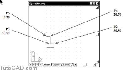
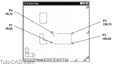
8) Pick Draw + Line and hold your crosshairs near P1 until the coordinate read-out says 10.0000,40.0000,0.0000 & then left-click to use that point. Move your crosshairs 2 GRID dots to the right and then left-click to use that point.

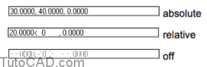
The coordinate read-out in the lower left corner of the AutoCAD window can be in three different states at prompts for the next point.
- it can be Off, it can show the absolute coordinates of the crosshairs or the crosshairs position relative to the last point.
- you can left-click in the coordinate read-out (or press F6) to cycle through these three different states.
9) Left-click on SNAP points P2, P3, P4 and P5 below to create 4 more LINEs & press <enter> to terminate Line.
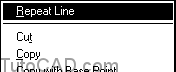
10) Right-click in the drawing area to invoke a shortcut menu and select Repeat Line.
11) Press <enter> at the first Line prompt for the starting point to use the Continue feature of Line. Move your crosshairs around (without picking) to observe how the next LINE is anchored at the last point of your last Line command.

12) Move your crosshairs to the SNAP point for the start of your first LINE segment and left-click to use that point. Then press <enter> to terminate Line.
If you terminate Line you can easily repeat Line and Continue with the same point you used for the endpoint of the last Line command.
- press <enter> at the first Line prompt (instead of picking a point) to begin where your last LINE segment (or ARC object) ended.
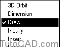
13) Find the Line button in the Draw toolbar and left-click on this button to invoke the Line command.
If the Draw toolbar is not displayed you can right-click on ANY toolbar button to invoke a shortcut menu.
- there must be a check beside Draw in this shortcut menu for the Draw toolbar to be visible.
- select Draw in the shortcut (if there is not a check beside Draw).
- the Draw toolbar is initially docked on the left side of the AutoCAD window but it may have been changed on your system.
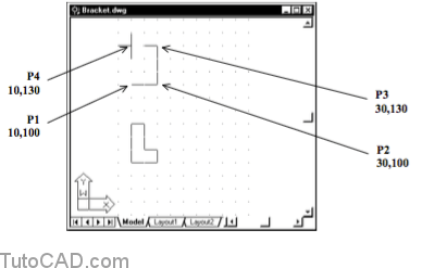
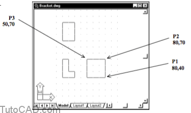
14) Move your crosshairs to P1 ( 10,100,0 ) and left-click to use this point as the start of the next LINE. Then pick the points P2, P3 and P4 but do NOT complete the rectangle or terminate Line (yet)
15) Right-click in the drawing area to invoke a shortcut and then select the Close option.
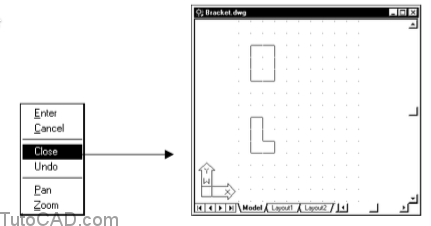
When you use Close the Line command is automatically terminated.
16) Right-click in the drawing area to invoke a shortcut again and select Repeat Line. Then click on the points P1, P2, P3 and P4 but do NOT complete the rectangle or terminate the Line command (yet).
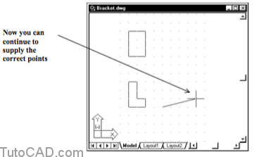
It is easy to make a mistake when you supply points for the Line command but you do not have to start all over again if you do.
- you can type U to undo points that you supplied in the current Line command (right back to the start point if desired).
- you can also right-click to select Undo from a shortcut instead.17) Enter U three times at the keyboard to undo the last three points you supplied to the current Line command.
18) Pick points P1, P2 and P3 then use Close.
19) Add the last 2 LINEs & Save changes to Bracket.dwg.
