Welcome to this comprehensive guide on the CHAMFER command in AutoCAD! Whether you’re a seasoned professional or a budding designer, understanding the power of this versatile tool is essential to enhance the aesthetics and functionality of your design work. This guide will not only provide an overview of the CHAMFER command but also delve deeper into its various modes and options. But that’s not all! We’ll also explore its practical applications, access points, and how it relates to other AutoCAD commands. Moreover, we have included a FAQ section to answer common questions about this command to facilitate a more in-depth understanding.
Overview of the CHAMFER Command
The CHAMFER command in AutoCAD is an incredibly versatile and useful tool that is mainly used for drawing beveled corners or edges. It allows designers to create beveled or angled edges, enhancing the realism and complexity of their designs. It’s often utilized in architectural and engineering contexts, adding a level of precision and detail to objects.
Detailed Description of the CHAMFER Command
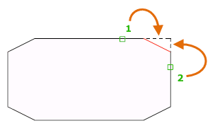
The CHAMFER command in AutoCAD operates by taking two lines or edges as input and then produces a beveled edge that joins these lines at an angle. The command is flexible and allows the user to define the length or the angle of the bevel, creating a wide range of different shapes and structures.
The following types of objects can be chosen when defining a chamfer or bevel:
- 2D polylines
- 3D solids and surfaces (not available in AutoCAD LT)
- Lines
- Rays
- Xlines
Different Modes and Options of the CHAMFER Command
There are several modes and options within the CHAMFER command:
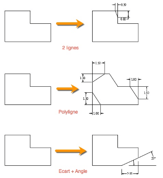
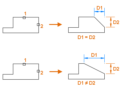
- Distance: This option lets you define the distances along the two selected lines where they will be beveled.
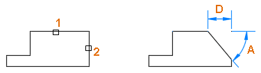
- Angle: This option allows you to define one distance and one angle for the bevel.
- Method: The CHAMFER command has three methods you can choose from – Distance or Angle.
Reasons for Using the CHAMFER Command
The CHAMFER command is beneficial in many ways:
- Design Enhancement: CHAMFER adds depth and detail to otherwise flat or plain designs.
- Model Realism: In real-world objects, sharp edges are rare. Adding chamfers makes your design look more realistic.
- Safety Considerations: In practical manufacturing, chamfering edges can eliminate sharp corners that could be hazardous.
Accessing the CHAMFER Command
Here are the different ways you can access the CHAMFER command:
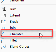
Menu: Modify → Chamfer
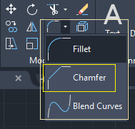
Ribbon: Home tab → Modify panel → Chamfer
Toolbar: Modify toolbar → Chamfer

Command Bar: Type CHAMFER or CHA and press Enter.
Shortcut: CHA
Step-by-Step Guide to Using the CHAMFER Command
- Type
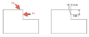
CHAMFERorCHAin the command line, then pressEnter. - Specify the first chamfer distance (this could be the length of the line or the distance along the line where the chamfer starts).
- Specify the second chamfer distance.
- Select the first line or polyline segment.
- Select the second line or polyline segment.
Related AutoCAD Commands
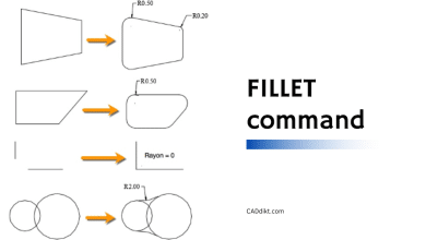
- FILLET: This command is similar to CHAMFER but creates a rounded corner between two lines.
- JOIN: This command connects two or more objects to make the single object.
- OFFSET: This command creates parallel or concentric copies of lines, polylines, circles, arcs, or splines.
Sometimes, you may want to chamfer an entire polyline or a set of lines in one command. In that case, the CHAMFER command has a polyline mode.
Using the polyline Mode
- Type
CHAMFERorCHAin the command line, then pressEnter. - Select a polyline to chamfer all corners or vertices in a single action.
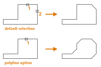
The CHAMFER command in AutoCAD introduces a chamfer line at every vertex of a 2D polyline where two straight line segments intersect. These newly formed chamfer lines then integrate as new segments within the existing polyline. However, it’s important to note that this modification doesn’t occur if the Trim option is configured to ‘No Trim’.
Troubleshooting the CHAMFER Command
Lines are not adjacent
Ensure that the lines you want to chamfer meet at a point or are at least extended to meet. The CHAMFER command cannot work if there is a gap between the lines.
The chamfer distance is too large
If the chamfer distance is larger than the length of the line, the command will fail. Ensure that your chamfer distance is less than the length of the shortest line you want to chamfer.
FAQ: AutoCAD CHAMFER Command
1. Why is chamfer used in AutoCAD?
The chamfer command in AutoCAD is used to create beveled corners or edges in a 2D or 3D drawing. This can enhance the visual appeal of a design, making it more detailed and realistic. In real-world manufacturing, chamfering also helps to eliminate sharp corners that could pose safety risks. This tool is incredibly useful in architectural and engineering designs, where precision and detail are key.
2. What is the chamfer edge command in AutoCAD?
The chamfer edge command is a specific command used to create a beveled edge on a 3D solid object in AutoCAD. This command allows the user to specify the width and angle of the bevel, providing flexibility to the designer. It is often used in designing furniture, architecture, and machine parts.
3. How do I show chamfer in AutoCAD?
To show a chamfer in AutoCAD, you can use the “CHAMFEREDGE” command. This will create a chamfer on the edge of a 3D solid or surface. You can then specify the base surface, distance, and angle to create a visible chamfer.
4. What is a chamfer tool for?
A chamfer tool is used to create a beveled edge at the intersection of two surfaces. In manufacturing, a chamfer tool often refers to a type of cutting tool used to create this bevel in materials such as wood or metal. In CAD software like AutoCAD, the chamfer tool provides a way to create this beveled edge digitally in a design.
5. How do you get chamfer edges?
In AutoCAD, you can get chamfered edges by using the “CHAMFER” or “CHAMFEREDGE” commands. These commands allow you to select two lines or edges and specify the chamfer distances. The program will then create a beveled edge or corner at the intersection of the selected lines.
6. How do you chamfer a polyline in AutoCAD?
You can chamfer a polyline in AutoCAD by using the “CHAMFER” command with the “LOOP” option. After starting the command and entering ‘L’ at the prompt, you can select the polyline. AutoCAD will then chamfer all corners of the polyline based on the current chamfer distances.
7. What is the effect of chamfer?
The chamfer command creates a beveled edge at the intersection of two lines or surfaces, which can add depth and complexity to a design. This can make a drawing appear more realistic, as sharp corners are rare in real life. In a physical object, a chamfer can also make an edge safer by removing a sharp corner.
8. How do I smooth edges in AutoCAD?
To smooth edges in AutoCAD, you can use the “FILLET” command for rounded edges or the “CHAMFER” command for beveled edges. For 3D objects, you may also use the “SMOOTHMESH” command to smooth the entire surface of an object.
9. How do you edit chamfer?
In AutoCAD, you can edit a chamfer by first deleting the existing chamfer and then recreating it with the desired settings. Another option is to use the “PROPERTIES” command to modify the chamfer’s dimensions if it was created as a separate entity.
10. What is the fillet and chamfer command in AutoCAD?
In AutoCAD, both the fillet and chamfer commands are used to create rounded or beveled corners, respectively. The fillet command creates a rounded corner between two lines, while the chamfer command creates a beveled (angled) corner
11. What is an example of a chamfer?
A common example of a chamfer in real life is the beveled edge on a table or countertop. This beveled edge, often at 45 degrees, removes the sharp corner and adds a pleasing aesthetic touch. In construction, chamfers are frequently used on concrete structures such as beams and columns to prevent chipping.
12. Why do chamfer finish lines?
Chamfer finish lines are used in various design and manufacturing applications. In manufacturing, chamfering is often used to eliminate sharp corners, making the object safer to handle. In machining, chamfers are applied to aid in the alignment of parts and to ease the assembly process.
13. Why is it called a chamfer?
The term “chamfer” comes from the Latin “canta,” meaning “flange,” and the French “chanfrein,” meaning “bevelled edge.” It essentially describes a transitional edge between two faces of an object, often created at a 45-degree angle.
14. Which is better chamfer or fillet?
Choosing between chamfer or fillet depends on the application. A chamfer tends to be better when you need a part to fit into another at an angle since the chamfered edge will guide the parts together. On the other hand, a fillet can provide a higher strength to weight ratio and is typically better for reducing stress concentration, so it’s often used in aerospace and automotive applications.
15. What is edge chamfering?
Edge chamfering refers to the process of creating a bevelled edge at the intersection of two surfaces. This can be done physically, using a chamfering tool on a material, or digitally in CAD software like AutoCAD using the “CHAMFER” command.
16. Is a chamfer always 45 degrees?
No, a chamfer isn’t always 45 degrees. While 45 degrees is a common angle for chamfers, it can be any angle less than 90 degrees. The angle and distance of the chamfer can usually be specified in CAD software like AutoCAD.
17. What is the disadvantage of chamfer?
The main disadvantage of a chamfer is that it may not be as effective at distributing stress as a fillet. This is because a chamfer creates a sharp transition between surfaces, which can become a stress concentration area. However, in terms of aesthetics and practical assembly, chamfers can still be a preferred choice.
18. Can chamfer command be used on 3D objects in AutoCAD?
Yes, the chamfer command can be used on 3D objects in AutoCAD. This is typically done using the CHAMFEREDGE command, which creates a beveled edge on a 3D solid or surface.
19. How can I adjust the chamfer distance in AutoCAD?
The chamfer distance can be adjusted when initiating the CHAMFER command. After starting the command, you’ll be prompted to specify the first and second chamfer distances. By inputting new distances, you can adjust the size of the chamfer.
20. What is the difference between chamfer and taper?
While both chamfer and taper involve angling of edges, they serve different purposes. A chamfer is a beveled edge connecting two surfaces, usually at a 45-degree angle. A taper, on the other hand, is a gradual, smooth, and uniform reduction or increase in the diameter or thickness of an object.
21. What is the difference between chamfer and radius?
A chamfer is a flat beveled edge, often at a 45-degree angle, while a radius is a rounded edge. When using the CHAMFER command in AutoCAD, you create a straight line connecting two adjoining lines or surfaces. The FILLET command, in contrast, creates a curved, radius surface between two lines or surfaces.
22. Can you chamfer an arc in AutoCAD?
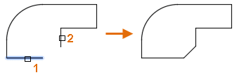
Yes, you can chamfer an arc in AutoCAD. When the CHAMFER command is initiated, you can select the arc as one of the two entities for chamfering. This will create a beveled edge at the selected end of the arc.
23. Can you undo a chamfer in AutoCAD?
Yes, you can undo a chamfer in AutoCAD using the UNDO command, which reverts the drawing to the state before the CHAMFER command was applied. Alternatively, you can use the ERASE command to remove a chamfer if it was created as a separate object.
24. Can you chamfer a circle in AutoCAD?
You cannot directly chamfer a circle in AutoCAD because a chamfer requires two lines or surfaces. However, you can convert a circle into a polyline or divide it into segments, and then chamfer the corners formed by the segments.
25. Is chamfering necessary in AutoCAD?
While chamfering is not necessary for every design in AutoCAD, it provides aesthetic and practical benefits in many situations. Chamfers can make a design appear more realistic and detailed, as well as making physical objects safer by removing sharp corners. For these reasons, it’s a useful command to know when using AutoCAD.
Final Thoughts
The CHAMFER command in AutoCAD is a critical tool for creating realistic, detailed, and practical designs. From providing aesthetic appeal to ensuring safety by eliminating sharp corners, it’s a command that designers should have a strong grasp of. We hope this guide has provided you with a robust understanding of the CHAMFER command and its various applications. Remember, the best way to master this command, like any other, is through consistent practice. So, keep exploring, experimenting, and creating with AutoCAD. Happy designing!