Among the AutoCAD commands, the ARRAY command is a true workhorse, capable of creating complex, repeating patterns of objects with precision and ease. Whether you’re designing a bolted connection, a series of lights on a ceiling, or a row of buildings, the ARRAY command can save you an incredible amount of time and effort.
This comprehensive guide aims to delve into the ARRAY command, exploring its nuances and vast capabilities. We’ll cover everything from its basic usage to its different modes and options, step-by-step tutorials, reasons for use, and related commands. Furthermore, to resolve any lingering queries, we’ve also included a detailed FAQ section addressing common questions about the ARRAY command.
So, whether you’re a beginner looking to understand the fundamentals or an experienced AutoCAD user seeking to refine your skills, this guide is designed with you in mind. Let’s dive in!
Overview
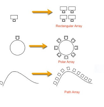
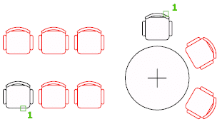
The ARRAY command in AutoCAD is a powerful tool designed for creating multiple copies of objects in a pattern or arrangement. With ARRAY, you can replicate drawings in a linear pattern (like a row of chairs), a circular pattern (like the numbers around a clock), or a rectangular pattern (like a grid of streetlights).
Detailed Description of ARRAY Command
The ARRAY command operates under three major modes:
- Rectangular Array (ARRAYRECT): Creates copies in a rectangular pattern (rows, columns, and levels). Suitable for creating a grid-like arrangement.
- Polar Array (ARRAYPOLAR): Creates copies in a circular pattern around a central point or axis. Ideal for radial arrangements.
- Path Array (ARRAYPATH): Distributes copies along a path or a portion of a path. Useful when arranging objects along a pre-determined curve or line.
Each mode offers different options for specifying the distance between objects, the number of objects, and the angle between them.
Reasons to Use ARRAY Command
The ARRAY command can save significant time and reduce errors when creating repeated patterns in a drawing. Instead of manually copying, placing, and aligning each object, ARRAY automates this process with precision and consistency.
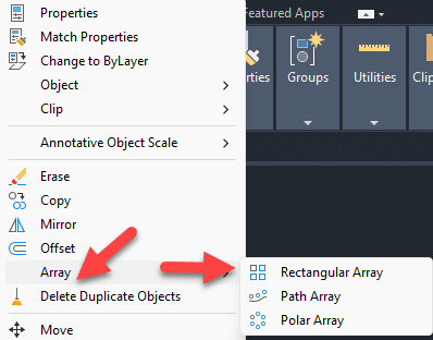
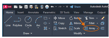
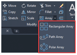
How to Access the ARRAY Command
Accessing the ARRAY command can be done in several ways:
- Menu: From the “Modify” menu, select “Array”.
- Ribbon: In the Home tab under the Modify panel, click on the “Array” command.
- Toolbar: If the Modify toolbar is active, you can click on the “Array” button.
![]()
- Command Bar: Type “ARRAY” in the command line and press Enter.
- Shortcut: The keyboard shortcut for ARRAY is AR, followed by Enter.
How to Use ARRAY Command
- Choose the type of array you want to create by typing ARRAYRECT, ARRAYPOLAR, or ARRAYPATH in the command line.
- Select the objects you want to include in the array.
- Specify the parameters for your array. For example, with a rectangular array, you would specify the number of rows, columns, and levels and the distance between them.
- Press Enter to create the array. AutoCAD will then create the array based on your specifications.
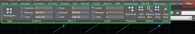
How to Use ARRAYRECT Command: Step-by-Step
The ARRAYRECT command is a feature of AutoCAD that allows you to create a rectangular pattern of object copies. Here’s a step-by-step guide on how to use it:
Step 1: Open Your Drawing
Begin by opening the drawing where you want to create an array. Choose the object or group of objects you wish to array.
Step 2: Select ARRAYRECT Command
To activate the command, type ARRAYRECT into the command line and press Enter. Alternatively, you can find it on the ‘Modify’ panel under the ‘Home’ tab in the Ribbon, then click on the rectangular array button.
Step 3: Select Objects
After you’ve activated the ARRAYRECT command, AutoCAD will prompt you to select objects. Click on the object(s) you wish to array and then hit Enter when you’re done.
Step 4: Specify the Number of Rows, Columns, and Levels
Next, AutoCAD will ask for the number of rows (in the Y direction), columns (in the X direction), and levels (in the Z direction). Input the desired number for each and press Enter after each input. By default, the levels parameter is set to 1, creating a 2D array.
Step 5: Specify the Distance Between Rows and Columns
AutoCAD will then ask you to specify the spacing between each row and column, and the height between each level. Again, input the desired distance and press Enter after each. This distance is measured from the base point of one object to the base point of the next object in the array.
Step 6: Confirm the Array
At this point, you should see a preview of your array. If it looks correct, press Enter to confirm and create the array. If not, you can type ‘E’ and press Enter to edit the settings.
And there you go! You’ve created a rectangular array. Remember, this array is associative by default, meaning it behaves as a single object. If you want to edit individual elements, you can convert the array to a non-associative array.
Step 1: Open Your Drawing
Start by opening the drawing where you want to create the polar array. Choose the object or group of objects you wish to array.
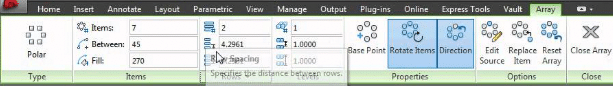
Step 2: Select ARRAYPOLAR Command
To activate the command, type ARRAYPOLAR into the command line and press Enter. Alternatively, you can find it on the ‘Modify’ panel under the ‘Home’ tab in the Ribbon, then click on the polar array button.
Step 3: Select Objects
After the ARRAYPOLAR command is activated, AutoCAD will prompt you to select objects. Select the object(s) you wish to array and then press Enter when you’re done.
Step 4: Specify the Center Point
Next, AutoCAD will ask for the center point of the array, which is the point around which the objects will be duplicated in a circular pattern. Click anywhere in your workspace to set the center point.
Step 5: Specify the Number of Items
Now, AutoCAD will prompt you to enter the number of items, or the number of copies of the object(s) you want in the array. Input the desired number and press Enter.
Step 6: Specify the Angle Between Objects
AutoCAD will then ask you to specify the angle to fill (measured counterclockwise) with arrayed objects. Input the desired angle in degrees and press Enter. The default is 360 degrees, which will create a full circle of copies.
Step 7: Confirm the Array
You should now see a preview of your polar array. If it looks correct, press Enter to confirm and create the array. If it doesn’t, you can type ‘E’ and press Enter to edit the array’s settings.
That’s it! You’ve created a polar array. Like the rectangular array, the polar array is associative by default. If you need to manipulate individual elements, you can convert the array to a non-associative array.
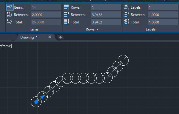
How to Use ARRAYPATH Command: Step-by-Step
The ARRAYPATH command in AutoCAD allows you to distribute object copies along a path or a series of connected paths. Here’s a step-by-step guide on how to use it:
Step 1: Open Your Drawing
Open the drawing where you want to create the path array. You’ll need both an object (or group of objects) you wish to array and a path along which the objects will be arrayed.
Step 2: Select ARRAYPATH Command
Activate the command by typing ARRAYPATH into the command line and press Enter. Alternatively, you can find it on the ‘Modify’ panel under the ‘Home’ tab in the Ribbon, then click on the path array button.
Step 3: Select Objects
After activating the ARRAYPATH command, AutoCAD will prompt you to select objects. Select the object(s) you want to array and then press Enter to confirm your selection.
Step 4: Select the Path
AutoCAD will then ask for you to select the path along which the objects will be arrayed. The path can be a line, polyline, 3D polyline, spline, helix, arc, circle, or ellipse. Click on the path you want to use.
Step 5: Specify the Method and Number or Distance
Next, AutoCAD will prompt you to specify the array type (Measure or Divide) and the number of items or the distance between the items. For the Measure method, you’ll enter the distance between items. For the Divide method, you’ll input the total number of items in the array. Press Enter after your input.
Step 6: Specify Alignment and Tangent Direction
You’ll be prompted to specify whether the items should align to the path. Type ‘Yes’ or ‘No’ and press Enter. For objects that are not perpendicular to the tangent direction of the path, you can control their orientation with the Align to Path option.
Step 7: Confirm the Array
Finally, you’ll see a preview of your path array. If it looks correct, press Enter to confirm and create the array. If it doesn’t, type ‘E’ and press Enter to edit the array’s settings.
And that’s it! You’ve created a path array. By default, the path array is associative. If you need to manipulate individual elements, you can convert the array to a non-associative array.
Related AutoCAD Commands
- COPY: Creates copies of objects but without the automated patterned placement.
- MIRROR: Creates a mirrored duplicate of an object.
- ROTATE: Rotates an object around a base point.
YouTube Links Explaining the ARRAY Command
Here are some useful YouTube tutorials to help understand the ARRAY command better:
Rectangular Array:
Polar Array:
Path Array:
Beyond the basic usage, ARRAY offers some advanced capabilities that can enhance your drawing process:
- Associative Arrays: By default, arrays in AutoCAD are associative, meaning they behave as a single object. You can select and modify the entire array at once, which can be a major time-saver. If you want to edit individual elements, you can convert the array to a non-associative array.
- Editing Arrays: The ARRAY command is not just a one-time operation. You can modify arrays after they have been created. This includes changing the count and arrangement of objects in the array, the distance between them, and other parameters.
Tips and Tricks for Using ARRAY
- Use Preview: Before finalizing your array, use the preview option to see what your array will look like. This can save you time by preventing mistakes before they happen.
- Adjust Base Point: For polar and path arrays, consider moving the base point of the object before creating the array. The base point is the point around which the array is created, so changing the base point can give you more control over the arrangement of objects.
Troubleshooting Common Issues
Sometimes you may encounter issues while using the ARRAY command. Here are a few common problems and their solutions:
- Objects are not arranging correctly: Check to make sure your distances and counts are correct, and that you’re using the right type of array for your needs.
- Cannot select individual objects in the array: The array might be associative. Use the BURST command to convert it to a non-associative array.
FAQ: How to use ARRAY command?
1. How Can I Use ARRAY for 3D Models in AutoCAD?
AutoCAD’s ARRAY command isn’t limited to 2D objects; it’s also handy for replicating 3D models. For instance, if you’re creating a structure that involves repetitive elements, such as a high-rise building with identical floors, ARRAY can expedite the process significantly. When using ARRAYRECT, you can specify a third parameter, levels, in addition to rows and columns, to duplicate objects in 3D space.
To use ARRAY for 3D models, you follow a similar process as for 2D objects, making sure to adjust your view and work in a 3D-friendly workspace. Remember to keep an eye on the UCS (User Coordinate System) to ensure correct placement of the 3D objects.
2. What is the Difference Between Associative and Non-Associative Arrays?
In an associative array, the arrayed objects act as a single unit, making it easier to manipulate the entire group simultaneously. If you make changes to the source object or adjust the array’s parameters, all arrayed items will update automatically.
On the other hand, a non-associative array treats each object as separate. This gives you the flexibility to edit individual elements without affecting the rest of the array. However, changing the original object or the array parameters will not update the arrayed items.
3. How Can I Edit the Source Object in an Array?
To edit the source object in an array, you need to access the array’s source object by using the ARRAYEDIT command. Enter ARRAYEDIT into the command line, select the array you want to modify, and AutoCAD will isolate the source objects for editing. After making changes, you can exit the editing state, and AutoCAD will automatically update the entire array.
Remember that this is only possible with associative arrays. If you’re dealing with a non-associative array, you’ll need to modify each object individually or recreate the array after adjusting the source object.
4. Can I Array Along a Curve or Irregular Path?
Yes, the ARRAYPATH command allows you to distribute objects along a curve or irregular path. This feature can be particularly useful when designing curved roads, railway lines, or similar objects where a straight-line or circular pattern is not feasible.
After initiating ARRAYPATH, select the object to be arrayed and the path along which it will be distributed. AutoCAD will then place the objects along the specified path, keeping a uniform distance between each object, according to the parameters you set.
5. How Do I Adjust the Spacing Between Objects in an Array?
The spacing between objects in an array is defined by the parameters you set during the array’s creation. In a rectangular array, you set the distance between rows and columns, while in a polar array, you define the angle between objects. For a path array, you specify the measure or the number of objects along the path.
If you want to adjust the spacing after creating the array, select the array and access the Array Contextual Tab in the Ribbon, where you can modify the between-item distances, counts, or angles.
6. What Does the ARRAY Command Do in AutoLISP?
In AutoLISP (AutoCAD’s programming language), the ARRAY command behaves similarly to its usage in regular command-line AutoCAD. It replicates an object along specified dimensions (rectangular), around a center point (polar), or along a defined path (path). You can use ARRAY in your AutoLISP scripts to automate repetitive tasks and enhance your productivity in complex AutoCAD projects.
7. What If I Need to Add More Objects to an Existing Array?
Adding more objects to an existing array can be accomplished by modifying the array properties. For an associative array, simply select the array, access the Array Contextual Tab in the Ribbon, and increase the count of items. The additional objects will be added according to the original array settings.
Remember, this feature is available only for associative arrays. If your array is non-associative, you may need to recreate the array with the desired number of items.
8. How Can I Create an Array with Varying Distances Between Objects?
Creating an array with varying distances between objects is not directly possible with the standard ARRAY command, as it is designed to maintain uniform spacing. For non-uniform arrays, consider using multiple array commands with different spacing parameters, or manually place copies of the object.
However, for a more automated approach, the Divide or Measure commands might be helpful. These commands place blocks or points along a line or curve at specified intervals, which could provide a workaround for non-uniform arrays.
9. How to Convert an Associative Array into a Non-Associative Array?
Converting an associative array into a non-associative one can be done using the EXPLODE or BURST command. Either of these commands will break the array association and treat each arrayed object as an individual element.
Be aware that once an array has been exploded, the link to the original source object is lost and changes to the source object or array settings will not update the exploded array.
10. Can I Use Different Objects in One Array?
The ARRAY command is typically used to duplicate a single object or a group of objects as a unit. However, if you want to array different objects, you might need to create separate arrays for each object or group of objects.
Alternatively, you could create a block that incorporates all the objects you want to array. You could then use ARRAY on the block. Remember, in this case, each arrayed instance will include all the objects in the block.
11. What Happens When I Copy an Array?
When you copy an array, AutoCAD creates an exact duplicate of the original array, including its properties and parameters. This means the copied array will maintain the same number of objects, arrangement, and spacing as the original.
Keep in mind that copying an associative array retains the association, meaning changes to the array settings will update all copies of the array. Conversely, if you copy a non-associative array, each copy is treated independently.
12. How Can I Rotate Objects in an Array?
The rotation of objects in an array depends on the type of array. In a polar array, objects are automatically rotated around the center point. For a rectangular or path array, the objects retain their original orientation by default.
If you want to rotate objects in a rectangular or path array, you may need to rotate the source object before creating the array or rotate each object manually after the array has been created.
13. How Do I Delete an Object from an Array?
Deleting an object from an array is straightforward for non-associative arrays—simply select the object and press Delete. For associative arrays, however, you must first convert the array to a non-associative one using the EXPLODE or BURST command. Once the array is non-associative, you can delete individual objects.
14. Why Can’t I See the Array after I Create It?
If you can’t see the array after creating it, several issues may be at play. It’s possible the array was created in a layer that’s currently turned off or frozen. Alternatively, the objects might be outside the current view, too small to see, or in a different plane in the case of 3D models. Check these potential issues to find the missing array. You might also want to use Zoom Extents to ensure that the entire drawing area, including your array, is visible.
15. Is It Possible to Modify the Shape of Arrayed Objects?
Modifying the shape of arrayed objects depends on the array type. For non-associative arrays, you can modify each object individually, but the changes won’t apply to the rest of the objects in the array.
For associative arrays, you can use the ARRAYEDIT command. This will allow you to edit the source objects of the array, and the changes will propagate to the entire array. If you need to make individual alterations to objects in an associative array, you might need to first convert the array to non-associative.
16. Can I Change the Layer of Objects in an Array?
Yes, you can change the layer of objects in an array. If the array is non-associative, simply select the objects, go to the Layer Control drop-down menu in the Home tab, and choose the desired layer.
For associative arrays, changing the layer will affect the entire array. To change the layer of individual objects within an associative array, you’ll need to convert the array to a non-associative array first.
In conclusion, the ARRAY command in AutoCAD is an indispensable tool for creating duplicate objects efficiently. The more you familiarize yourself with its features and options, the more you’ll be able to leverage its capabilities to streamline your design workflow.
Conclusion
The ARRAY command in AutoCAD is a fundamental tool for all designers and drafters, significantly streamlining the process of creating multiple instances of an object in your drawings. As we have seen throughout this guide, the ARRAY command is versatile, flexible, and relatively easy to use once you understand its various options and methods.
While it may take some practice to get the hang of it initially, the time and effort saved in the long run are undeniable. Use this command to its full potential, experiment with its different modes, and customize its settings to match your unique needs.
We hope this guide has provided you with a deeper understanding of the ARRAY command and its application in AutoCAD. Remember, the most effective way to learn is by doing, so don’t hesitate to open up AutoCAD and start experimenting with what you’ve learned here. The road to mastery begins with a single step, and you’ve just made significant strides in your AutoCAD journey. Happy designing!